English
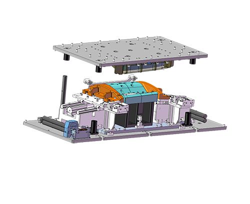
Joint Design for Vibration Welding
by Alex Lee of MP Sonic
Mob/Wechat/WhatsApp: +86-15918523336
Email: alex.lee@mp-sonic.com; alexlee2696@163.com
Join design for vibration welding concept:
1. Measurement of welding rib;
9. Ensure that the surface slope at vibration direction no over than 10 degree.
I. Welding Design Measurement

II. Bevel Angle of Welding Surface

III. Welding Design Construction

IV. Types of Welding Design

V. Support Design for Vibrtion Welding

VI. Usually Applied Joint Design for Vibration Welding