English
Introduction to Spin Friction Thermoplastic Welding
by Alex Lee
Mobile/Wechat/WhatsApp: +86-15918523336
Email: alexlee2696@163.com
I About Spin Welding Technology
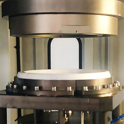 Spin welding is a kind of frictional joining technique in capability of producing strong, air-tight welding to parts with a circular-axis jointing, which with high bond strength / hermeticity requirements. During spin friction welding, one part half is held stationary in a holding fixture while the other one is rotated against it under pressure at a high speed normally 80~1600 rpm, which results friction at the touch area of two part halves (means the joining area) and causes the joining surfaces to melt until form fuse together, after which stop rotation and keep two part halves together under pressure until the interface of the jointing area cool down and become solidification.
During spin welding process, the rotational motion normally controlled by electrical motors or by pneumatic powered motor.
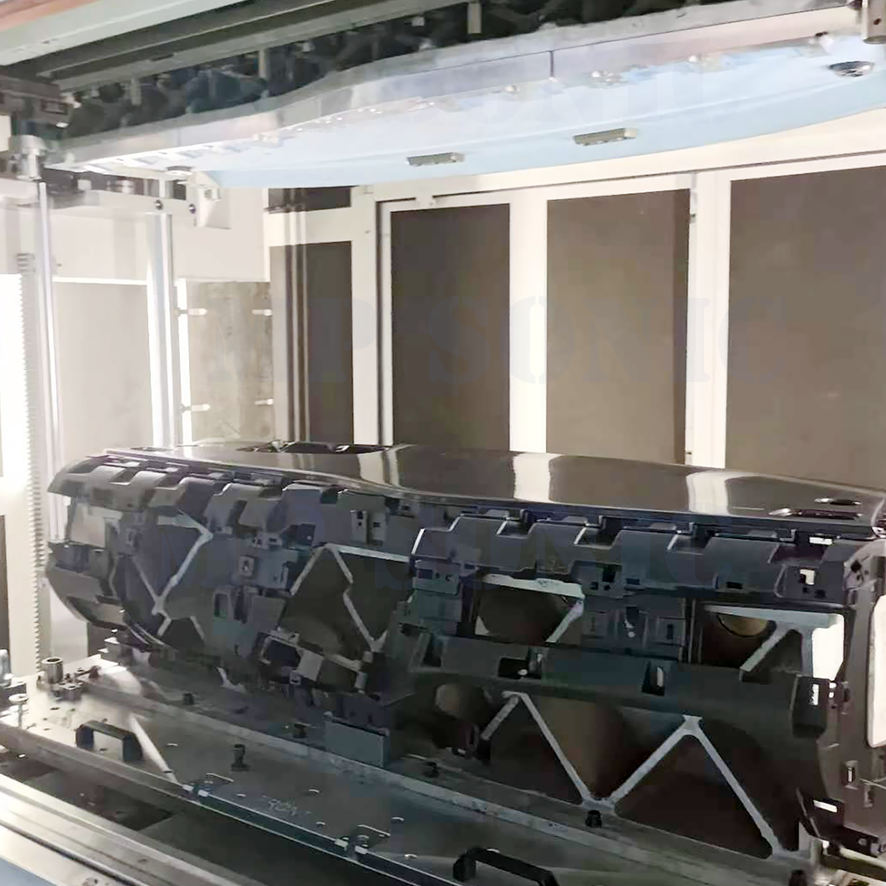
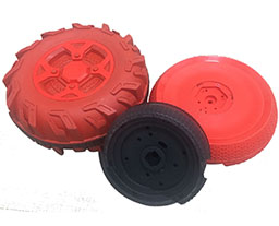
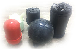
Spin welding can be applied for thermoplastic jointing or metal jointing. Here we study spin thermoplastic welding art only. Spin thermoplastic welding technique can be applied in many areas, such as automotive industry (eg. The assembly of manifold, brake oil tank, etc), house appliance industry (eg. The production of washer tank and washer balance ring), toy industry (child carriage wheel), medical appliance industry (eg.foreskin cutter), daily necessities industry (eg. Cups), etc.
Spin Welding Process:
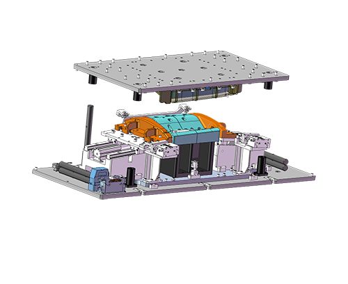
1. Loading part halves into fixtures;
2. Two parts move towards together;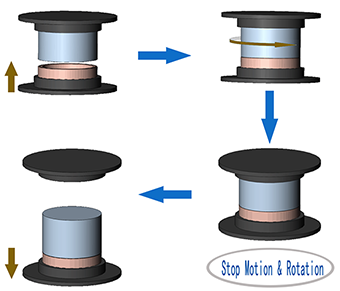
3. One part half rotates when two halves contact each other and keep two halves move together in tiny speed;
4. Stop rotation when the material is molten at the contacting interface, and keep two halves pressed together under pressure.
5. Upper jig release part machine apart parts from upper jig;
6. Lower jig release part and manual unload part from lower jig.
Spin Welding Process Advantages:
>High welding ability: can be applied to weld parts in round almost in no limit in diameter;
>Much shorter cycle time comparing to heat welding;
>Can be applied to the most kind of thermoplastic material;
>Spin welding is ideal for welding soft material such as PP, PE, etc;
>Spin welding is in ability to weld several dissimilar materials;
>No consumables, fumes or emissions, spin welding procedure is in advantage of lower production cost and environment-friendly;
>Spin welding result is in high strength, hermetic welds are typical.
>Economical: Low cost in equipment, welding tooling, maintenance and power consumption.
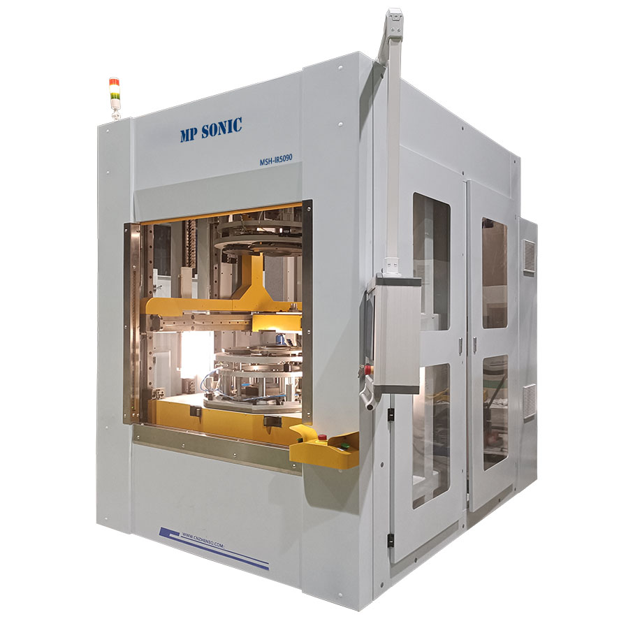
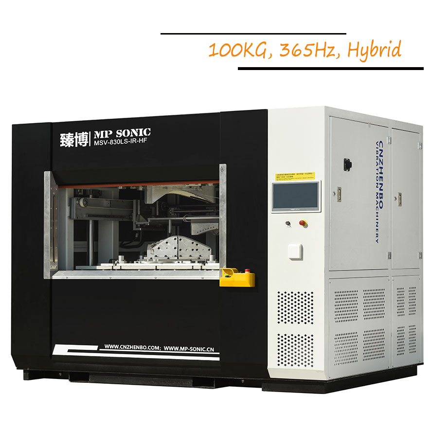
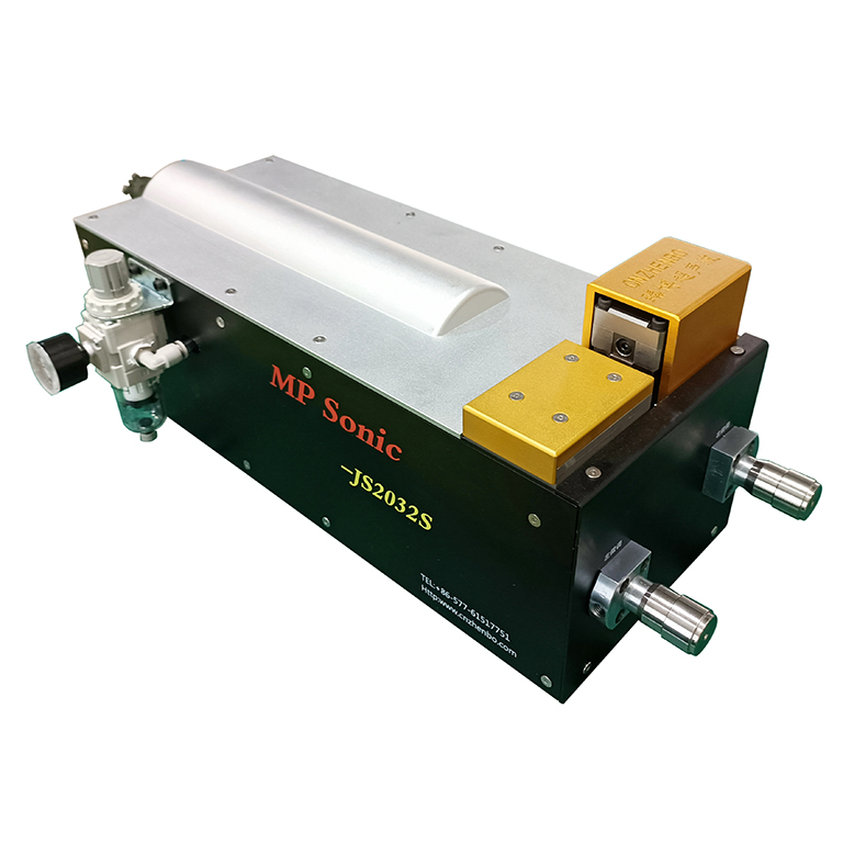
iBORTECH . MP Sonic makes spin welding machines in modular design along with customized specification.
II Material Weldable by Spin Friction:
III Types of Spin Welder.
1) Non-orientation Spin Welder:
A. Non-orientation Electrical Spin Welder, whose rotation is driven by electronic motor, with advantage of higher welding power. This kind of machine is requested by round plastic welding requiring less velocity without the need of orientation control in rotation. Machine mostly applied to welding parts in big diameter.
B. Inertial (Pneumatic) Spin Welder,whose rotation is driven by pneumatic motor. Before welding motion, it requests to store inertial energy. Inertial spin welding is with the advantages of higher speed which is good for soft materials. The all inertia energy will transferred to part, while the rotation is stopped by part-to-part contacting. Inertial spin welding is suitable for welding soft material requesting high speed or small thermoplastic part with no request of orientation.
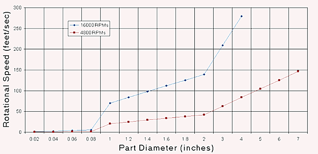
Parts to be welded by spin friction must be symmetry around the common axis ant the jointing interface to allow the parts rotate against each other. A proper rotation speed under pressure will be the critical parameter to gain good spin welding result. Here the speed of rotation not means RPM, but should be the circumference speed. The circumference speed (here called “CS”) in Feet/Second formula is: CS=Part Diameter*π*RPM/(Second*12).
According to the above formula, normally, to fit parts requirement, pneumatic motor can be slected as 4800RPM or 16000RPM, gears in various ratio can be selected basing on materials and diameter of parts.
Normally, if the diameter at the welding interface is less than 1’’, it suggests apply an electromagnetic brake incorporation for proper melting control.
2) Orientation Spin Welder: Orientation Spin Welder applies servo motors to control welding rotation. Servo controlled welding spindle is with advantage of higher power output (high rotation torque) and position is axis direction, speed in phases control. Orientation spin welder is applied to weld parts in big diameter, challenging material or thermoplastic assembling requesting orientation.
The most benefit of servo controlled welding spindle is: A. stop welding rotation at a specified points in high precision at the rotation degree to index parts match each others at mating points; B. it can control rotation in changing speed during welding process at different phases basing on thermoplastic material characteristics; C.It can fix at any rotation points to gain a convenient loading / unloading parts.
IV Force Control of Spin Welding
During spin welding process, machine is force two parts moving together and keeping contacting under pressure. Basing on parts material characters, parts dimension and welding quality requirement, it can apply pneumatic cylinder or servo motor to control the motion of welding jig and pressure forcing to parts.
A. Pneumatic cylinder, with the advantage of economical cost, easy control and high pressure force output. It is mostly applied for the welding with no requests of high control precision in welding depth and jig in light weight. The welding depths control of spin welding forced by pneumatic normally by mechanical stoppers;
B. Servo motor, the pressure is transferred from the rotation torque of servo motor. It is with the advantages of fast motion speed, quick reaction, high control precision and heavy jig loading. With servo motor motion control, it realizes the changeable motion speed during welding process at different phases according to requirement, high precision control in welding depth. It is mostly applied for challenging thermoplastic material, big parts or parts requests high precision in welding depth.
V Critical Parameters :
1. Rotation Speed - RPM(Round per Minute)
2. Weld Time or Numbers of Rotation Round
3. Contacting Force
4. Melding Force
5. Fusing (holding for cooling) Force