English
Ultrasonic Plastic Melting Technique Application
by Alex Lee Mobile/Wechat/WhatsApp: 86-15918523336, email: alexlee2696@163.com

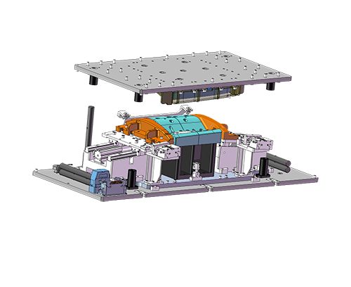
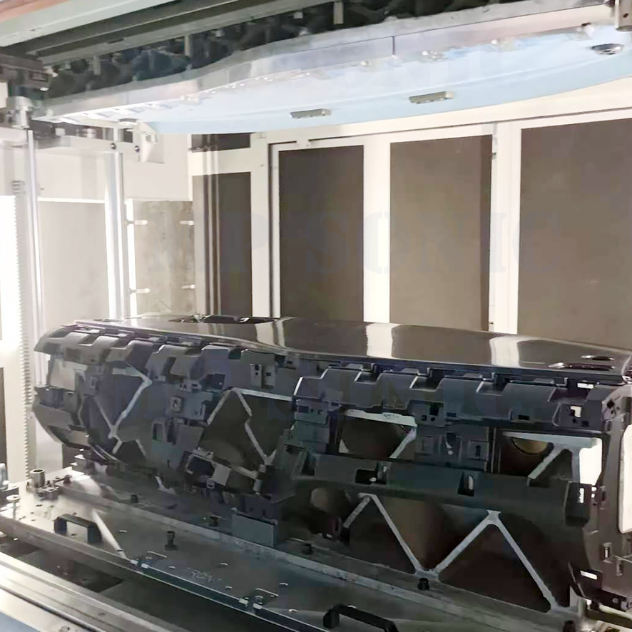
I. We apply thermoplastic melting procedure by ultrasonic technique for parts production including ultrasonic plastic welding, ultrasonic plastic stacking, ultrasonic spot welding, ultrasonic cutting, ultrasonic punching, ultrasonic gate cutting, etc. It means apply ultrasonic system to convert supplied 50/60 Hz electrical energy into mechanical oscillation energy in frequency of 15KHz or over and work on plastic work-pieces to melt material to achieve welding/sealing/bonding or cutting.
Main Parameters of ultrasonic Welding : welding time, holding time, pressure, energy, amplitude, welding depths, etc.
The ultrasonic head motion and welding force normally can be controlled by pneumatic cylinder or servo motor.
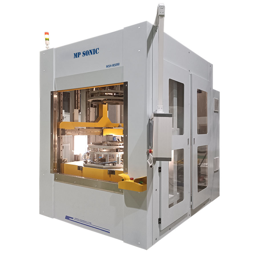
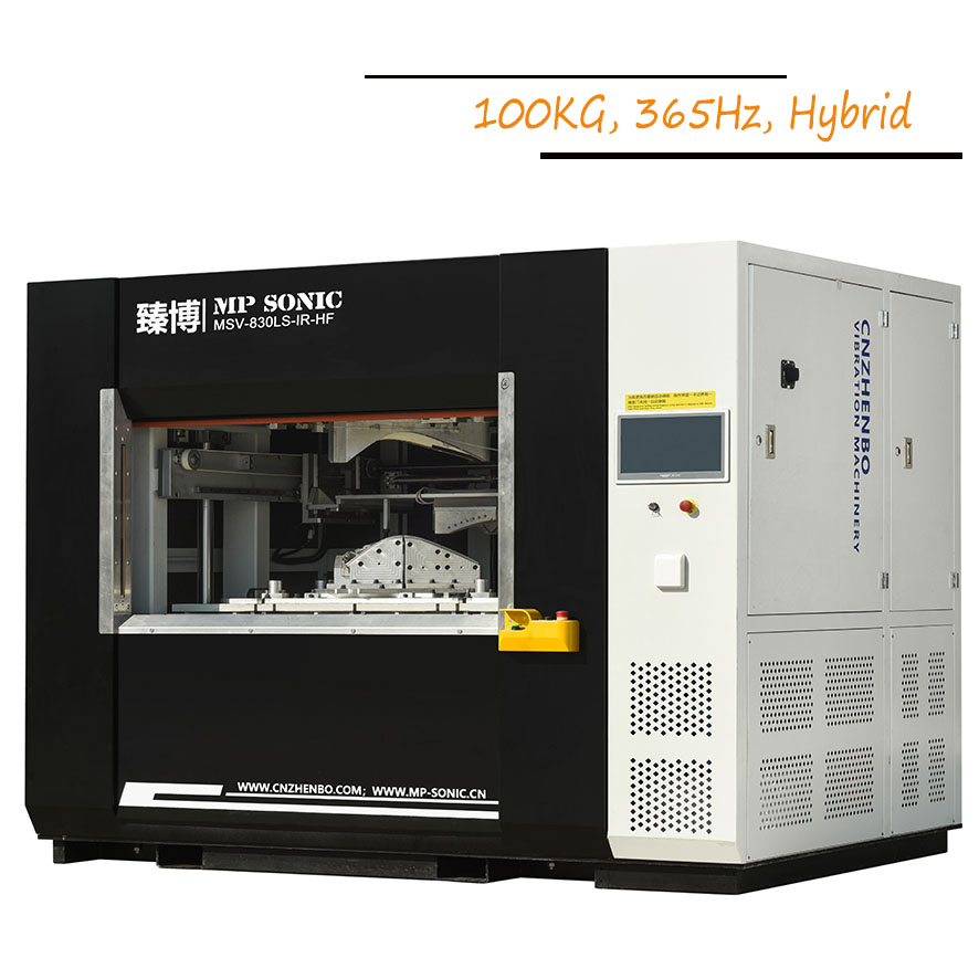
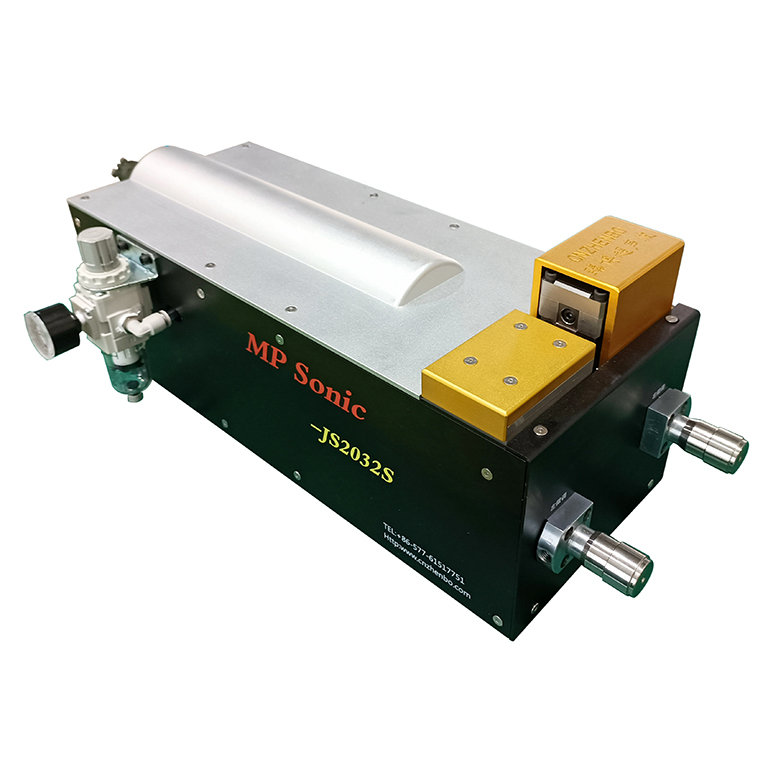
Check Standard Ultrasonic Welding Machines
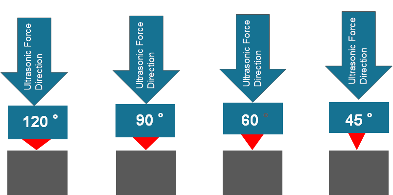
II. The critical parameters of ultrasonic welding including time, amplitude and pressure affects welding performance the mostly, which can be referred as below illustration.

II. Joint Desing for Ultrasonic Plastic Welding
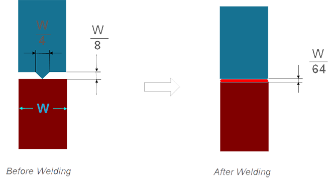
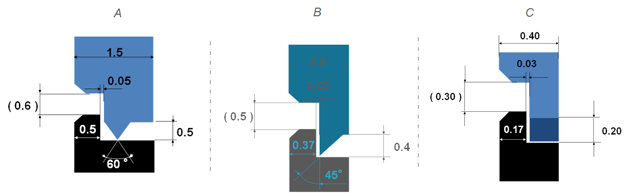
1. Energy Director design:
Energy director means the ultrasonic welding rib, which can make it easy focus ultrasonic energy to case material melting in short time. It case material displacement by molten thermoplastic material to form bonding.
2. Butt Joint Design
Butt Joint Design is mostly applied for ultrasonic welding with no high requirement. It is with advantages of simple design complex and small space requested.
This kinds of joint design provide better welding strength, air-tightness and material flash prevention than butt welding design, because the material displacement is kept inside of jointing area achieve more bonding at welding area.
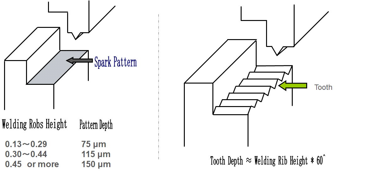
For some part ultrasonic welding, especially for some challenging material, it request energy direction design on the welding surface of the other plastic part half against the welding rib, for better friction by ultrasonic oscillation to generator heating energy and material melting.
5. Tongue & Groove Design
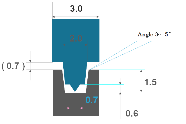
By tongue & groove joint design, the material displacement achieves the best welding strength and airtightness. And it is mostly applied for: A. Self-assembly; B. Flash prevention at both inner side and outer side.
6. Shear Joint Design
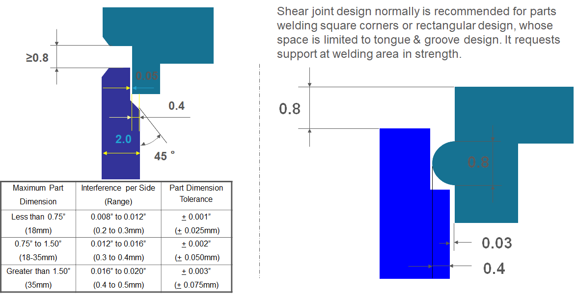
Shear joint design normally is recommended for parts welding square corners or rectangular design, whose space is limited to tongue & groove design. It requests support at welding area in strength.
This kinds of design mostly for large welding with high requirement in hermetic seal and welding strength when limited space for welding design. This kinds of design requests high injection precision.
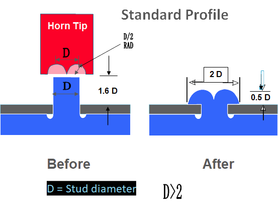
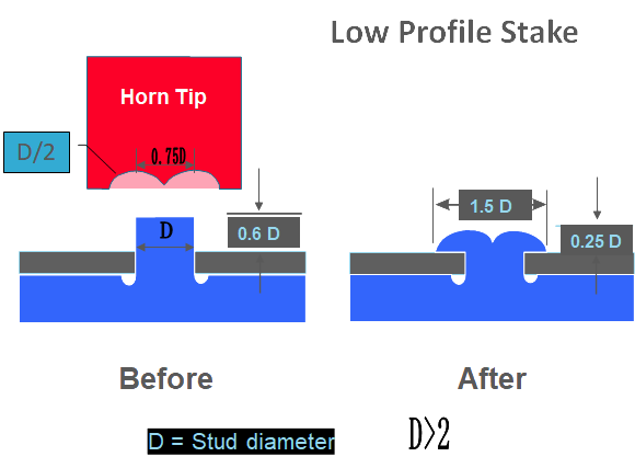
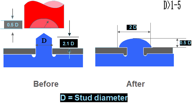
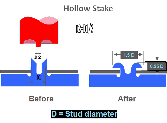
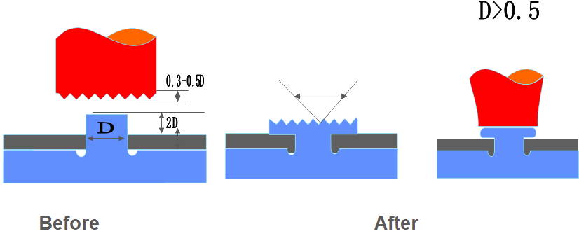
IV. Ultrasonic Plastic Stacking Design
1. Standard Profile Design
2. Low Profile Stake Design
. 
3. Half Ball Shape Design
4. Hollow Stake Design
5. None Cavity Tip Design
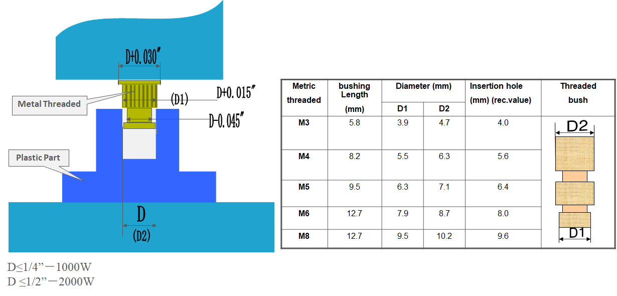
V. Ultrasonic Insertion Design
VI. Injection Gate Design for Ultrasonic Cutting
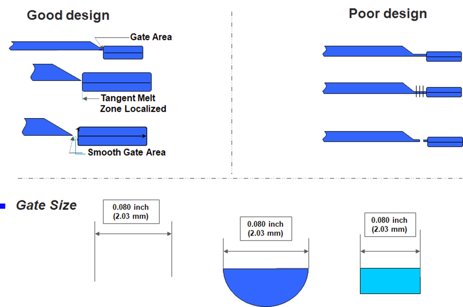
Above deisgns are applied for most parts process. It should be variated or modified basing on plastic parts actual geometirc design and material selected. It suggests you contact with us for welding anylysis before confirm the final ultrasonic process design.