English
Welding Design & Welding Tooling for Spin Welding
following up "Introduction to Spin Friction Thermoplastic Welding"
by Alex Lee Mob/Wechat/WhatsApp: +86-15918523336 Email alexlee2696@163.com
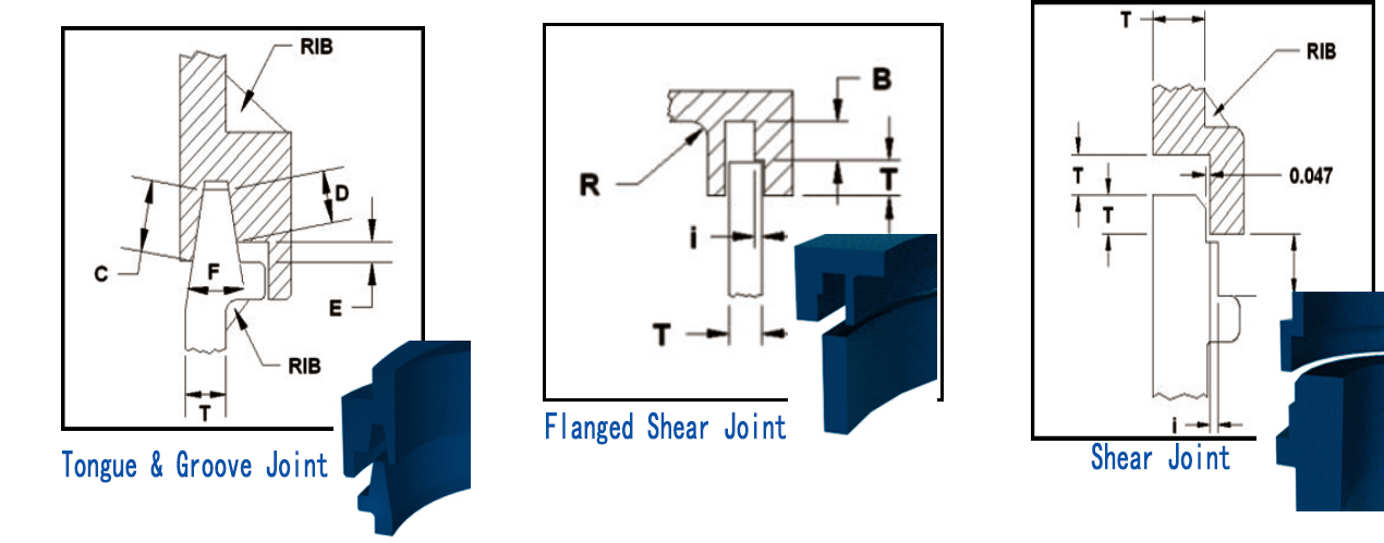
VI Spin Welding Joint Design.
Joint design is critical to spin welding joint in high quality. The welding area should be equal to or greater than a typical wall section of the parts to be welded. The jointing should provide sufficient part-to-part alignment. During joint design to spin welding on a part, it necessary to have below factors considered:
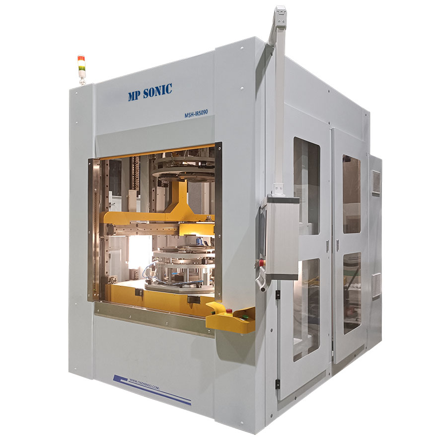
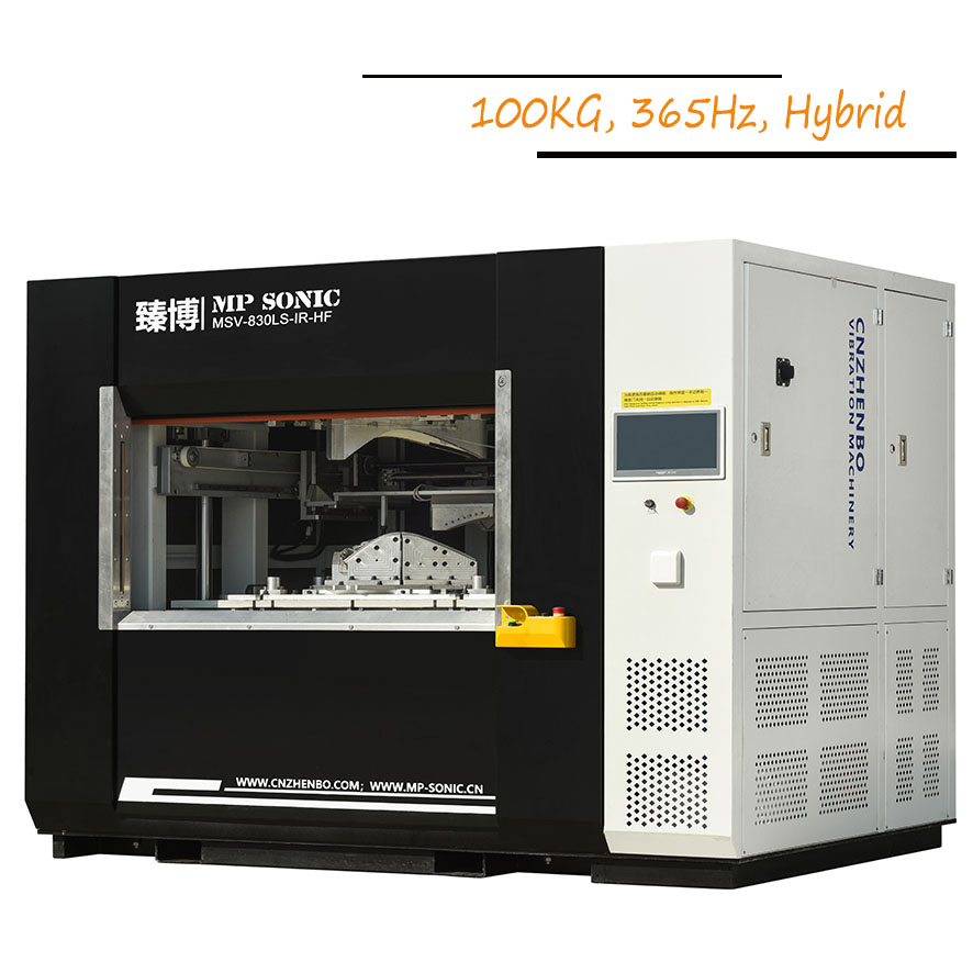
VII Spin Welding Tooling
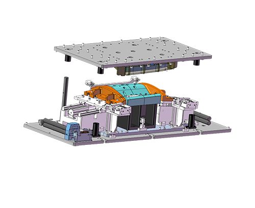
A set of spin welding tooling consists of: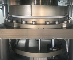
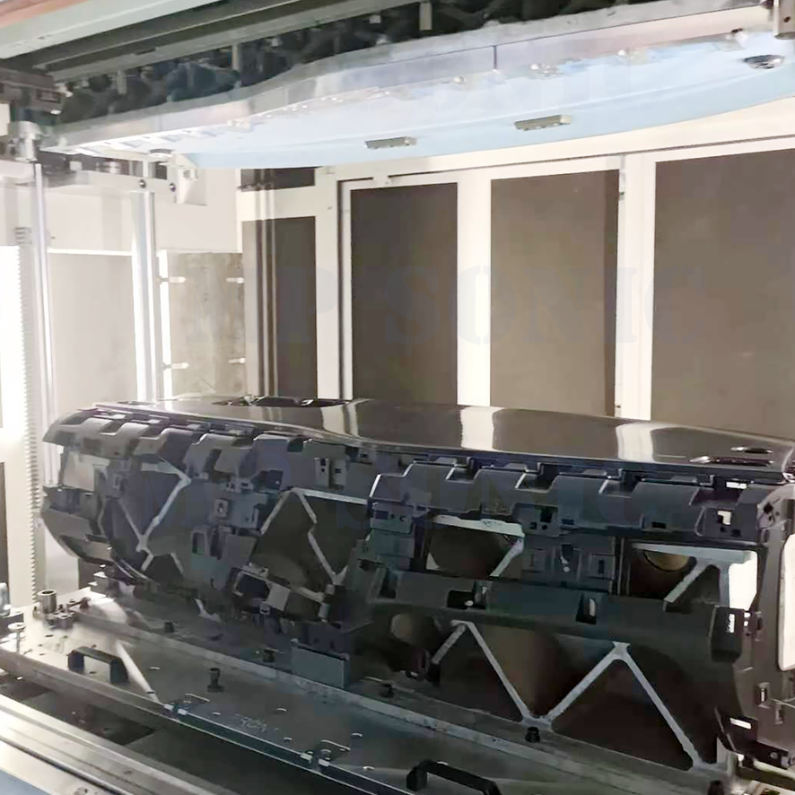
1 Driving jig: it means the rotational jig which driving the plastic part half spin at circular axis. The driving jig design should simple avoiding acting parts such as sliding block, clips, vacuum, etc, but also should ensure that the part to be held in the jig with not moving. The critical factor of the driving jig is the concentricity and weight of the jig, which might result success or failure of spin welding.
2 Stationary jig: it means the jig holding the other plastic halve with no rotation. On this jig, it should consider the easy loading and unloading parts, and should ensure parts will be held with no moving during process. Optional features such as ejection, sliding block, hook, vacuum pad, part detection, etc can be applied on stationary jig.
Normally, spin welding tooling is made of aluminum. And protect parts from hurting, it can apply silicon or others soft material in jig cavities contacting parts.
It should design jig weight the lighter the better, especially the driving jig to reduce the torque cased by inertia.